
Ideal Logic Combi 30 Installation Manual: A Comprehensive Plan
This detailed manual guides professionals through a safe and efficient installation of the Ideal Logic Combi 30, ensuring optimal performance and longevity.
The Ideal Logic Combi 30 is a highly efficient and reliable condensing combination boiler, designed to deliver both central heating and domestic hot water on demand. This manual provides comprehensive instructions for qualified heating engineers undertaking the installation process. It’s crucial to read and understand all sections before commencing work, ensuring adherence to current gas safety regulations and building standards.
This boiler boasts a compact design, making it suitable for a variety of installation locations. Proper installation is paramount for safe and efficient operation, maximizing its lifespan and minimizing potential issues. This guide will walk you through each step, from initial checks to final testing.
Safety Precautions & Warnings
Installation must be carried out by a qualified and competent Gas Safe registered engineer, adhering to all relevant regulations. Disconnect the gas and electricity supply before commencing any work. Always wear appropriate personal protective equipment (PPE), including safety glasses and gloves.
Ensure adequate ventilation during installation and operation. Carbon monoxide is a deadly, odorless gas – a carbon monoxide detector is strongly recommended. Never attempt to modify the boiler or use non-approved parts. Incorrect installation can lead to dangerous situations, including gas leaks, fire, or explosion. Prioritize safety at all times.
Unboxing and Component Check
Carefully unpack the Ideal Logic Combi 30, inspecting the carton for any signs of damage during transit. Retain the packaging for potential returns or warranty claims. Verify all listed components are present against the package contents list – a missing part halts installation.
Key components include the boiler unit, flue elbow, mounting bracket, and documentation. Check for visible damage to the boiler casing, pipe connections, and control panel. Report any discrepancies or damage to the supplier immediately. Do not proceed with installation if components are missing or damaged.
Package Contents Verification
Confirm receipt of all items listed on the accompanying packing slip. Essential components include the Ideal Logic Combi 30 boiler itself, a flue kit (comprising flue pipe and elbow), a mounting bracket for secure wall installation, and comprehensive installation/user manuals.
Also verify the presence of pipe connection kits, gaskets, and fixing screws. A separate bag should contain documentation regarding warranty information and contact details for support. Carefully cross-reference the physical contents with the packing list; any discrepancies must be reported immediately to avoid installation delays.
Identifying Key Components
Familiarize yourself with the boiler’s external features. Locate the gas inlet connection, clearly marked for appropriate gas type compatibility. Identify the cold water inlet and hot water outlet connections, noting their respective sizes. The flue outlet is crucial for safe combustion gas expulsion.
The control panel, featuring buttons and a display, manages boiler operation. Recognize the pressure relief valve and filling loop for system pressurization. Understand the location of the electrical connection points, essential for safe wiring. Proper component identification is vital for a correct installation.
System Requirements & Prerequisites
Before installation, verify essential system conditions. A suitable gas supply, matching the boiler’s specification (natural gas or LPG), is paramount. Ensure adequate electrical supply – typically 230V AC, with correct fuse rating. Existing gas pipework must be sized correctly for the boiler’s gas consumption rate.
The central heating system must be compatible and properly flushed. Water pressure should fall within the manufacturer’s recommended range. Confirm sufficient ventilation in the installation location. Adherence to these prerequisites guarantees safe and efficient operation.
Gas Supply Requirements

The Ideal Logic Combi 30 requires a compatible gas supply for safe operation. Natural Gas (G20) or LPG (G31) are acceptable, but the boiler must be configured for the correct type. Gas supply pressure must fall within the specified range – typically 20 mbar for natural gas and 28-30 mbar for LPG.
Existing gas pipes must be adequately sized to handle the boiler’s gas consumption. A gas soundness test is crucial post-connection. Always use qualified Gas Safe registered engineers for all gas work, adhering to current regulations.
Electrical Supply Requirements
The Ideal Logic Combi 30 necessitates a 230V/50Hz electrical supply. A dedicated, correctly fused circuit is essential, typically a 3A fuse. The boiler’s electrical connection must comply with current IET wiring regulations. Ensure the supply is earthed for safety.
A double-pole isolating switch, readily accessible, should be installed near the boiler. Qualified electricians must perform all electrical connections, verifying correct polarity and earthing. Incorrect wiring can cause malfunction or pose a safety hazard.

Installation Location Considerations
Selecting the right location is crucial for efficient and safe operation of the Ideal Logic Combi 30. The chosen area must offer adequate ventilation, complying with relevant building regulations, to dissipate combustion products. Proximity to gas and water supplies minimizes pipework length and potential heat loss;
Avoid installing in areas prone to freezing or dampness. Ensure sufficient space around the boiler for servicing and maintenance access. Consider noise levels and potential disruption during operation when selecting the location.

Ventilation Requirements
Proper ventilation is paramount for safe combustion and preventing carbon monoxide buildup. The Ideal Logic Combi 30 requires a sufficient air supply for optimal performance, adhering to all local and national building codes. Ensure flue gases can safely exit the property without obstruction.
Ventilation openings must not be blocked by furniture or other objects. Consider the room volume and boiler output when calculating ventilation needs. Always consult the full installation guide for specific ventilation requirements related to the installation type.
Proximity to Gas & Water Supplies
Efficient installation necessitates close proximity to both gas and water services, minimizing pipe runs and potential energy loss. The Ideal Logic Combi 30 should be located near existing gas pipelines and cold water inlets for streamlined connections.
Ensure adequate space around the boiler for maintenance and access to these connections. Avoid excessively long pipe runs, which can impact performance. Always adhere to regulations regarding gas pipe sizing and water pressure. Proper positioning simplifies future servicing and reduces installation complexity.

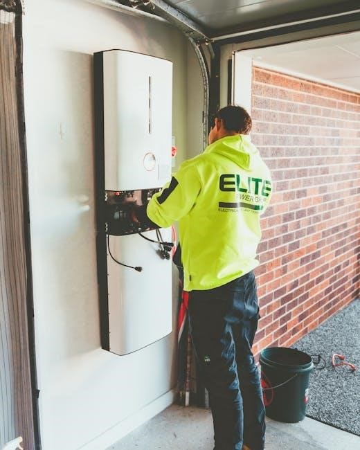
Mounting the Boiler
Securely mounting the Ideal Logic Combi 30 is crucial for safe and reliable operation. Begin by selecting a suitable, load-bearing wall capable of supporting the boiler’s weight, even when fully pressurized with water.
Utilize the provided mounting template to accurately mark drilling points. Employ appropriate wall plugs and screws, ensuring they are rated for the wall type. Verify the boiler is level after mounting, as this impacts performance. A stable and level mounting minimizes vibration and noise, extending the boiler’s lifespan.
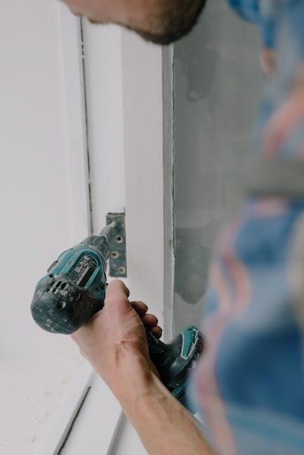
Wall Mounting Procedure
Begin by marking the mounting hole positions on the wall using the supplied template, ensuring accuracy. Drill pilot holes, then insert appropriate wall plugs – the type depends on your wall construction.
Carefully lift the Ideal Logic Combi 30 into position, aligning the mounting brackets with the prepared holes. Securely fasten the boiler using the provided screws, tightening them evenly. Double-check the boiler is level using a spirit level, adjusting if necessary. Finally, confirm the mounting is robust and can withstand the boiler’s weight.
Ensuring Secure Fixings

After initial mounting, rigorously inspect all fixings for tightness and stability. Utilize a torque wrench to confirm screws are tightened to the manufacturer’s specified levels, preventing loosening due to vibration.
Verify the wall plugs are securely anchored within the wall structure, capable of supporting the boiler’s full operational weight. Regularly check fixings during subsequent maintenance visits. Any signs of movement or strain necessitate immediate re-tightening or replacement of fixings to guarantee long-term safety and prevent potential hazards.
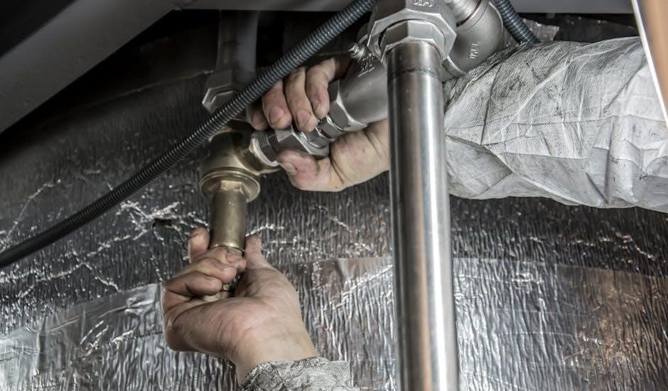
Plumbing Connections

Prior to commencing plumbing connections, ensure the mains water supply is isolated. Employ appropriate jointing compounds, compliant with current regulations, for all threaded connections to prevent leaks. Utilize flexible hoses where possible to accommodate thermal expansion and contraction, minimizing stress on rigid pipework.
Thoroughly flush the system to remove debris before connecting to the boiler. Double-check all connections for tightness after initial pressurization. Proper plumbing is crucial for efficient operation and preventing damage to the boiler’s internal components.
Connecting the Gas Supply

Gas connection work MUST be carried out by a Gas Safe registered engineer. Before connecting, isolate the gas supply and perform a leak test using a suitable gas leak detection fluid – never use a flame! Ensure the gas pipe is of adequate size for the boiler’s gas consumption rate.
Employ a suitable gas connector, compliant with relevant standards, and tighten securely. After connection, meticulously re-test for leaks. Verify the gas supply pressure is within the boiler’s specified operating range. Incorrect gas supply can compromise safety and boiler performance.
Connecting the Water Supply (Cold & Hot)
Ensure both cold and hot water supplies are isolated before commencing work. Use appropriate speed fittings and copper pipe (or approved alternatives) for connections. Install filters on both inlet pipes to prevent debris from entering the boiler, protecting vital components.
Connect the cold water supply to the designated inlet, and the central heating return to the outlet. Thoroughly check all joints for leaks after pressurizing the system. Proper water connections are crucial for efficient heating and hot water delivery, avoiding potential damage.
Electrical Connections
Prior to any electrical work, completely isolate the mains power supply. Access the wiring terminal within the boiler’s control panel. Carefully follow the provided wiring diagram, ensuring correct connection of live, neutral, and earth wires. Utilize appropriately sized cable for the current rating, adhering to local regulations.
Double-check all connections for tightness and security. Proper earthing is paramount for safety; verify a secure earth bond. Incorrect wiring can cause malfunction or pose a serious electrical hazard, so proceed with caution and expertise.
Wiring Diagram Explanation
The wiring diagram, located inside the boiler’s control panel cover, illustrates the precise connections required for safe operation. It details the live (L), neutral (N), and earth (E) terminals, alongside connections for external controls like thermostats. Color-coding is used for clarity; brown is typically live, blue neutral, and green/yellow earth.
Pay close attention to the voltage requirements and ensure compatibility with your mains supply. Incorrect connections can damage the boiler’s control board. If unsure, consult a qualified electrician for assistance – never attempt wiring beyond your expertise.
Earthing & Bonding Procedures
Proper earthing and bonding are crucial for electrical safety, preventing electric shock and ensuring correct operation. Connect a dedicated earth wire (typically green/yellow) from the boiler’s earth terminal to the main earthing terminal of the property’s electrical system. Bonding ensures all metallic gas and water pipes are electrically connected to the earthing system.
Use appropriately sized bonding conductors and ensure connections are tight and corrosion-free. Regularly inspect these connections for integrity. Failure to correctly earth and bond the system can create a dangerous electrical hazard; always verify with a qualified electrician.
Filling and Pressurising the System
Before initial start-up, the heating system must be thoroughly filled with water and pressurised to the manufacturer’s recommended level (typically between 1 and 1.5 bar). Open all radiator valves and locate the system filling loop – usually near the boiler. Slowly open the filling loop to allow water to enter the system, monitoring the pressure gauge.
Close the filling loop once the correct pressure is reached. Check for any leaks throughout the system, including radiators, pipes, and boiler connections. Bleed any trapped air from radiators to ensure efficient heating performance.
Initial Start-Up and Testing
Following filling and pressurisation, proceed with the initial start-up. Turn on the gas supply to the boiler and switch on the electrical power. The boiler’s control panel will initiate a self-diagnostic sequence. Observe the display for any error codes, consulting the error code section if necessary.
Test both the hot water and central heating functions. Verify correct water temperature and heating output. Check for any unusual noises or leaks during operation. Confirm the flue is operating correctly and venting safely to the outside.
Control Panel Overview & Functionality
The Ideal Logic Combi 30 features a user-friendly control panel with a clear LCD display and intuitive button layout. The display shows current system status, temperature settings, and any active error codes. Buttons allow adjustment of heating schedules, hot water temperature, and boiler mode (auto, manual, off).
Explore the menu options to access advanced settings, including frost protection and scale reduction programs. Familiarize yourself with the reset procedure and the function of each indicator light for efficient troubleshooting and operation.
System Settings & Configuration
Proper configuration of the Ideal Logic Combi 30 is crucial for optimal performance and efficiency. Access the settings menu via the control panel to customize heating schedules, tailoring them to your lifestyle. Adjust the hot water temperature to your preference, balancing comfort and energy savings.
Configure frost protection settings based on your location’s climate. Explore advanced options like modulation rate and system pressure adjustments. Remember to save all changes and document your settings for future reference, ensuring consistent and reliable operation.
Troubleshooting Common Issues
Encountering problems with your Ideal Logic Combi 30? Low pressure is often resolved by repressurising the system, following the instructions carefully. No hot water can indicate a blocked plate heat exchanger – descaling may be necessary. Check the gas supply if the boiler won’t ignite, ensuring it’s turned on.
Error codes provide valuable diagnostic information; consult the error code section for specific solutions. If issues persist, always consult a qualified heating engineer to avoid further complications and ensure safe operation.
Error Codes and Their Meanings
The Ideal Logic Combi 30 utilizes a comprehensive error code system for diagnostics. Code 101 typically indicates low water pressure, requiring system repressurization. A Code 103 suggests a flame sensing issue, potentially needing a burner inspection. Error 104 often points to a gas supply problem – verify the gas valve is open.
Consult the full error code list within this manual for a complete understanding. Addressing these codes promptly prevents further damage and ensures efficient boiler operation. Always prioritize safety and seek professional help if unsure.
Regular Maintenance Procedures
Consistent maintenance extends the lifespan of your Ideal Logic Combi 30. Annually, a qualified engineer should inspect the flue for blockages and test combustion efficiency. Check and clean the air intake and filter regularly – typically every six months – to maintain optimal airflow. Inspect pipework for leaks and corrosion, addressing any issues promptly.
Record all maintenance activities; Following this schedule ensures reliable performance and prevents costly repairs. Neglecting maintenance voids the warranty and compromises safety. Prioritize professional servicing for complex tasks.
Descaling the Boiler
Regular descaling is crucial for maintaining the efficiency of your Ideal Logic Combi 30. Hard water causes limescale buildup, reducing heat transfer and potentially damaging components. Descale the boiler every one to two years, depending on water hardness in your area.
Use a suitable descaling solution specifically designed for combi boilers, following the manufacturer’s instructions carefully. A qualified engineer should perform this task to ensure safety and prevent damage. Ignoring descaling leads to reduced performance and increased energy bills.
Winter Preparation & Frost Protection
As winter approaches, preparing your Ideal Logic Combi 30 is vital to prevent freezing and potential damage; Ensure the system is adequately insulated, particularly exposed pipes. Check the condensate pipe for blockages, as frozen condensate can cause boiler lockout.
Set the system to a minimum temperature, even when the property is unoccupied, to prevent frost damage. Regularly inspect for leaks and address them promptly. Consider a professional winter health check for peace of mind and optimal performance during colder months.
Contact Information & Support Resources
For technical support, troubleshooting assistance, or to report issues with your Ideal Logic Combi 30, please utilize the resources provided; Visit the official Ideal Heating website for FAQs, downloadable manuals, and online support forums.
You can also contact their dedicated customer support team via phone at [Insert Phone Number Here] or email at [Insert Email Address Here]. Ensure you have your boiler’s serial number readily available when contacting support for efficient assistance. Registered installers can access exclusive resources online.